Motorcycle fairing design has evolved beyond aesthetic appeal, merging aerodynamics, strength, and engineering precision. This holistic examination will delve into three critical aspects: advanced design and engineering diagrams, compatibility dimensions, and the regulatory standards shaping fairing production in China. Each chapter will illuminate how detailed diagrams can drive decisions for business owners, ensuring enhanced performance and customer satisfaction.
null
null
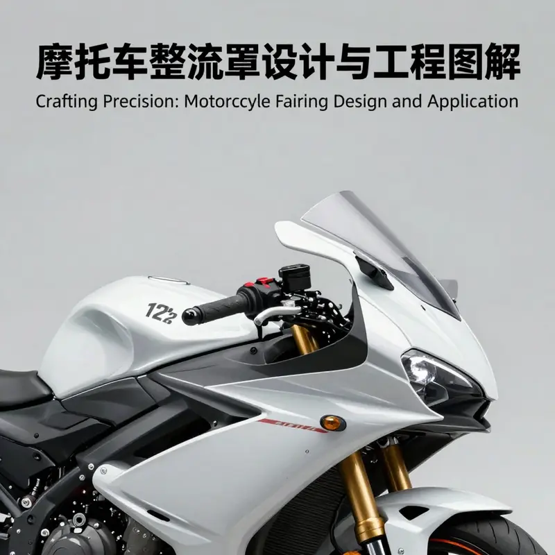
Sizing the Profile: Engineering Diagrams and the Compatibility of Motorcycle Fairings
The size and geometry of a motorcycle fairing are not mere styling choices. They are the critical interfaces where aerodynamics, rider protection, structural integrity, and manufacturing practicality converge. In modern engineering practice, the fairing is treated as a subsystem rather than a decorative skin. Its dimensions must accommodate a complex set of constraints: the mounting points on the frame, the contours of the fuel tank and cockpit, the space for sensor housings, and the need to maintain ground clearance and rider clearance across a wide range of speeds and riding positions. Achieving this requires a measurement discipline and a modeling discipline that begin long before any part leaves the tool room. Designers rely on precise three dimensional representations, not just for the shape itself but for every hole, tab, and window that determines how a kit will fit on a bike. The result is a design language that reads like a map of interfaces as much as a surface profile. When done well, the fairing becomes a harmonic integration of air flow, structural load paths, and assembly logistics, all expressed through dimensions that can be checked, replicated, and scaled across production runs and aftermarket variants.
The dimensional conversation around fairings begins with the mounting geometry. The three dimensional CAD diagrams capture the exact locations of install holes, the distances between mounting studs, and the alignment angles that ensure the panel sits flush with the riders cockpit and the tank line. These are not abstract coordinates; they translate directly into clamp forces, gasket compressions, and the subtle gaps that prevent rubbing or interference with adjacent components. In practice, engineers compare these dimensions against the vehicle frame reference frame, checking that edges align with the fairing lines and that the profile remains consistent when seen from multiple viewpoints. The dimensional data also informs the tolerances that govern production. A kit that fits perfectly on one frame might be snug or misaligned on another if the tolerance envelope is not carefully defined and controlled. In other words, the chapter on fairing sizing is really a chapter on managing fit through the discipline of precise geometry.
From a performance standpoint, the geometry of the fairing is a direct lever for aerodynamic efficiency. The wind tunnel and computational fluid dynamics studies that accompany a sizing exercise map how different surface curvatures, thicknesses, and chord lengths influence the drag coefficient and the pressure fields around the rider. In the most advanced programs, these analyses feed back into the 3D topology optimization models that sculpt the external surfaces while preserving or improving structural stiffness. The goal is not simply to reduce drag; it is to shape the wake, minimize separation points, and ensure a stable pressure distribution that helps the bike accelerate efficiently and ride with predictable stability. The fidelity of the fairing dimensions matters here because even a small deviation in a mounting plane or an edge curvature can perturb the boundary layer and alter the overall aerodynamic performance. A well sourced set of engineering diagrams translates into reliable simulation inputs, enabling engineers to push the envelope without introducing blind spots in the fit or the performance.
To ground this discussion in the standard that governs modern fairing engineering, it is useful to summarize the key performance indicators and the tolerance expectations that appear across authoritative technical norms. The national standard for fairing technology emphasizes three pillars: impact resilience, thermal stability, and aerodynamic diligence. The impact criterion requires that at a representative highway speed the fragments do not travel beyond a specified distance when a collision occurs. The thermal criterion demands that the chosen materials maintain their shape and integrity across a wide temperature range, from subfreezing to hot ambient conditions, without cracking or deforming. The aerodynamic criterion frames the acceptance in terms of a measured drag coefficient, including a tolerance band that ensures the final assembly does not deviate beyond a narrow percentage from the design target. These clauses are not abstract; they translate into clear dimensional targets. The mounting holes must line up within tight positional tolerances, the inter panel clearances must be maintained, and the interfaces with other assemblies must stay within a few millimeters of the intended geometry across the operating envelope. When manufacturers talk about compatibility, they are implicitly describing a contractual expectation that the dimensions, tolerances, and interfaces are repeatable and traceable across batches of production.
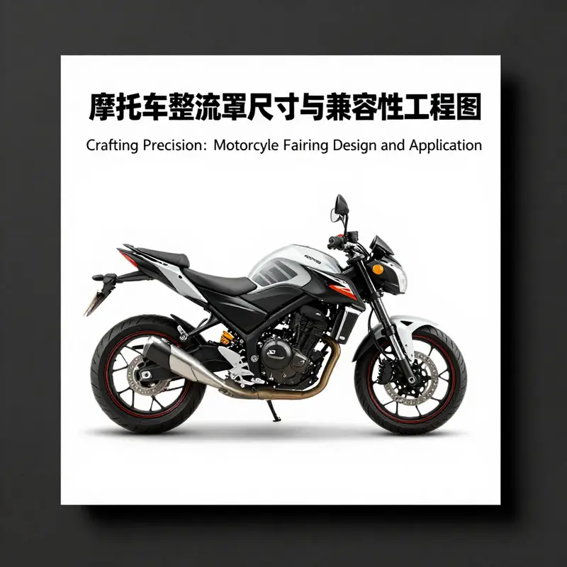
In practice, the spectrum of compatible fairing sizes expands through both factory grade kits and the aftermarket ecosystem. A factory grade package often provides a complete set that is precisely matched to a model year, with 3D diagrams that show the exact hole patterns and rib locations necessary to secure the part to the frame while not impinging on the fuel line or the cockpit shrouds. The aftermarket range, by contrast, tends to present a broader matrix of fitment options to accommodate variations in model generation and regional production changes. This is where the dimension data becomes the most valuable tool for installers and fabricators. A well documented set appears as a layered data package: standard outer shell geometry, a separate set of mounting hole coordinates, a tolerance table for clearances between panels and between the fairing and primary vehicle assemblies, and interface geometry that supports 3D printed or machined adapters for nonstandard frames. The combination of these elements makes it possible to plan fitment with confidence and to predict where issues might arise before any physical prototype is cut or molded.
The narrative of sizing also intersects with the realities of manufacturing. The production process imposes its own constraints, including mold cavity layouts, injection points, and post mold trimming. The selection of materials for the fairing panel depends on the thermal and impact requirements, but the final choice is also a function of how the part will be pressed into the assembly line and how many features the tool can reliably reproduce. The dimensional integrity across production is maintained through a feedback loop that links the CAD diagrams to physical measurement programs on the shop floor. Tolerances are not merely numbers; they become the practical language through which engineers communicate about what needs to be kept consistent to avoid misalignment or interference in the finished vehicle. A 30 millimeter discrepancy, for instance, might seem trivial on a single panel but can cascade into misalignment of mounting tabs, gaps around seam lines, or even sensor occlusion when the fairing is installed. The lesson is that dimension control is an every day discipline, not a one off specification.
The role of professional three dimensional models in this process cannot be overstated. A model that contains not only the exterior geometry but also the precise location of install holes, latch joints, and interface features becomes the primary reference for fit checks, reverse engineering, and mass production. In many cases, these models exist in formats that facilitate collaboration across design, tooling, and manufacturing teams. The format STEP is commonly used for its ability to capture robust geometric information and platform neutral interoperability. The availability of such digital references makes it feasible to simulate the entire assembly sequence in a virtual environment, verify the alignment of every fastening point, and even plan the assembly fixtures for automated lines. It is in this digital translation of the physical object that the dimensioned fairing truly earns its status as a diagram of compatibility. When a new kit enters development, engineers begin with a base geometry that tracks the intended surface silhouette, then layer in the installer specific data such as mounting hole coordinates and clearance tolerances to ensure the final part can be integrated with a range of chassis variants without custom adaptation.
The practical takeaway for designers and technicians is that the geometry of a fairing is a live element in the design process. It is handled with the same rigor as engine or chassis tolerances because it defines how the vehicle behaves in air and how it can be assembled, maintained, and upgraded. The process often begins with a compact but comprehensive set of dimensional data that includes the full set of reference points for mounting, the minimum and maximum permissible clearances, and the locations where panels interlock. A well prepared data package helps avoid common pitfalls such as edge contact with fuel lines or instrument panels, misalignment of the side panels with the centerline, or interference with the steering or front suspension under compression. It also supports downstream processes, enabling accurate nest programming for cutting or molding, precise hole drilling on the assembly line, and reliable replication of the same fit on subsequent production cycles or regional variants. In essence, the dimensions become the universal language that keeps the fairing and the vehicle in harmonious operation across different contexts and generations.
To connect the theory with practical references, design teams frequently consult catalog resources that summarize fitments by model family and generation. These catalogs provide a quick visual and dimensional check against the CAD data, ensuring that the chosen fairing line will align with mounting points and will not require nonstandard adapters. They also offer guidance on the range of compatibility for aftermarket kits, where dimension data often includes a mounting hole coordinates map and a clearance tolerance chart that helps users anticipate fitment challenges. When exploring the dimensional language for a given model family, it is natural to reference a catalog that organizes the data by chassis and year. For instance, a collection page focusing on a particular family can provide the essential pointers for a compatibility decision and offer a direct pathway to the installation diagrams that accompany the product. In the larger scheme, these catalogs act as living repositories of dimensioned knowledge, continuously updated to reflect changes in frame revisions, sensor placements, or fairing thicknesses that influence the assembly geometry. For readers who want to see how industry practice translates into a real world fit, a curated catalog such as the Yamaha fairings collection can provide a practical map of the landscape of compatibility. See here for a representative collection that demonstrates how fitment is presented in a structured way: Yamaha fairings collection.
Yet the story does not end with mounting holes and clearance charts. The ability to verify compatibility across generations of a model line is also a function of digital libraries that store detailed 3D drawings and interface geometry. Modern suppliers and engineering partners publish a structured set of resources that accompany each fairing kit. The 3D CAD diagrams reveal the exact pocketing where fasteners pass and how the fairing interacts with the frame under load. The interface geometry for 3D printing provides practical data for developers who want to validate fit with rapid prototyping before committing to a full production tool. The STEP based assembly diagrams support multi part integration planning and help teams anticipate how the fairing will locate itself within a complete assembly sequence on the shop floor. When dimension data is aligned with rigorous material behavior analyses, the final product can be optimized to deliver the best possible combination of air flow, weight, and protection. The upshot is that sizing the fairing is not an isolated task but a core element of a broader engineering program that seeks to harmonize the bike geometry with aerodynamic performance and manufacturing repeatability.
In addition to the engineering logic, the human dimension of the work remains essential. The people who design and install these components must listen to the subtle cues from the physical fit during test rides. A well sized fairing yields not only improved downforce management and reduced drag, but also a more predictable impression in the rider cockpit: the wind noise and buffeting feel balanced, the hand and knee contact points tested, and the visual line of sight preserved. The installer, whether a factory technician or an enthusiastic hobbyist, relies on the clarity of the dimension data to make informed choices about which kit to purchase and how to adjust mounting positions to accommodate minor frame variations. The result is a practical choreography of dimension, tolerance, and fit that keeps the entire system aligned under how the bike is used in the real world. This is why the dimensioning of fairings is never just about the shape; it is about the fidelity of the whole system to the rider experience and the performance targets embedded in the engineering plan.
For readers who want to explore how dimension data is compiled and validated in practice, professional 3D CAD resources provide a revealing window into the real world of fairing engineering. The digital models feature not only curves and silhouette lines but also the exact coordinates of a network of holes and latches that secure every panel into its final position. By reviewing these models, engineers can validate fitment without resorting to lengthy physical prototyping loops. This capability is particularly valuable when multiple versions or aftermarket variants must remain compatible with a single frame family. The STEP oriented assembly diagrams help the team to visualize the sequence of assembly, to detect potential clashes, and to plan the jigs and fixtures that will be used on the line. It is through this combination of geometry, tolerance discipline, and process planning that a fairing kit becomes a reliable part of the vehicle, capable of delivering both the performance gains that come from aerodynamic optimization and the durability required for real world riding.
In closing, the dimensional story of motorcycle fairings is a story about compatibility as a design principle. The sizes and interfaces are not an optional layer; they are the backbone of fit, assembly, and performance. The engineering diagrams, the tolerance charts, the 3D models, and the standardized references together constitute a rigorous workflow that keeps the fairing aligned with the vehicle and with the rider’s expectations. When teams invest in robust dimensioning and comprehensive documentation, they enable faster, more reliable production and easier aftermarket customization, all while sustaining the safety and aerodynamic efficiency that define high performing fairing systems. The path from a surface sketch to a fully integrated, dimensionally sound fairing is a sequence of disciplined steps where every millimeter of difference matters and every interface is a carefully protected interface. For those who want to explore further, the digital model repositories and catalog presentations offer a practical gateway to that disciplined practice. External resources and formal standards underscore the shared responsibility of designers, manufacturers, and regulators to keep fairing sizing precise, traceable, and repeatable across the life of a model family. External reference for extended technical context is provided at the end of this chapter to support deeper study into the CAD and fabrication aspects of fairing geometry. The discipline of fairing sizing is thus both a technical and a practical art, one that helps riders benefit from optimized performance and confident, repeatable fitment across a broad spectrum of machines and upgrades.
Shaping the Shield: Chinese Standards and Industrial Practice in Motorcycle Fairing Manufacturing
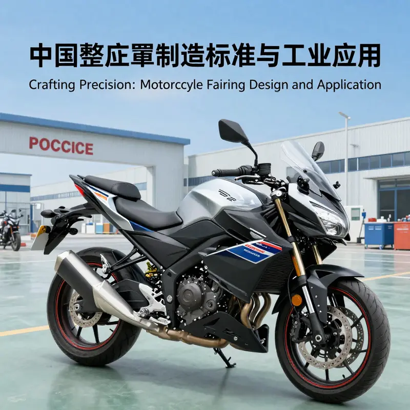
The motorcycle fairing diagram, at first glance a map of curves and mounting holes, is more than a cosmetic shell. It is the interface between aerodynamics, structural integrity, and user experience. In China, the evolution of fairing manufacturing has moved along two converging tracks that echo far beyond the edge of the bike’s fairing itself: a robust, standardized approach to composite parts in wind power and aerospace, and a growing, tightly regulated domestic ecosystem that translates those high-performance practices into motorcycle applications. This chapter traces how standards developed in distant sectors—wind turbines and space payloads—thread through design philosophy, materials selection, and manufacturing processes and ultimately shape how engineers draft a fairing diagram for a modern, high-performance motorcycle. It is a narrative of how abstract performance targets become concrete, production-ready geometry and how a united standard system anchors both the supplier and the rider in a shared expectation of safety, reliability, and aerodynamic efficiency.
The Chinese standardization scene for composite fairings began with a recognition: a fairing must withstand the rigors of real-world operation while preserving the delicate balance between airflow and rider protection. In wind power, where the rotor’s fairing-like blades and nacelles meet high-velocity, gusty environments, the core questions center on impedance, fatigue life, and durability under temperature swings. The national standard GB/T 29553-2013, entitled the wind power composite fairing standard, codified a comprehensive approach—from design intent to material choice, from manufacturing methods to performance verification and lifecycle management. This standard, steered by the national fiber-reinforced plastics standards committee and supported by leading composite manufacturers, created a shared benchmark that reduced variability, promoted domestic substitution for imported materials, and elevated manufacturing discipline across the sector. Even though the wind power domain might seem distant from two wheels, the core logic travels with it: a fairing diagram is not merely a CAD sketch; it is a contract between the designer, the fabricator, and the field tester, detailing how a part behaves as an object in flow, how it resists impact, and how it endures repeated thermal and mechanical cycles without degrading surface integrity or dimensional accuracy.
This standardized discipline is more than a safety net; it is a design language. In practice, the wind power standard encourages three-dimensional design tools and performance evidence to be integrated from the outset. Designers prepare 3D CAD diagrams, as mentioned in the industry literature, and insist on robust modal and finite element analyses to forecast how a fairing will deform under load and how its internal structure resists impact energy. The same principle extends to motorcycle fairings: the rider’s protection, the aerodynamics of the bodywork, and the ease of serviceability hinge on a disciplined process that respects strict tolerances and verified material properties. The motorcycle segment inherits this language through the same insistence on verification, albeit tailored to track performance and road reliability rather than turbine efficiency.
The aerospace influence deepens the argument. Space mission fairings—protective shells that carry satellites or payloads through the harsh venting, heat, and vacuum of launch—do not tolerate guesswork. In China, the aerospace sector has developed an elaborated body of practices around composite materials such as carbon fiber-reinforced polymers and honeycomb sandwich structures, paired with manufacturing techniques like resin infusion, autoclave curing, and automated layup. The industry’s attention to surface cleanliness, dimensional stability, and outgassing control translates into fairing design choices that prioritize a smooth external contour, consistent thickness distribution, and predictable thermal expansion. When a fairing sees sunlight, engine heat, and airframe exposure in a high-speed ride, the same concerns—delamination risk, moisture ingress, micro-cracking, and surface debonding—reappear with new urgency. The aerospace standardization program thus supplies a vocabulary for performance targets that can be adapted to motorcycles: a fairing should maintain structural integrity during high-load maneuvers; its surface finish should resist environmental attack; and its internal layout should accommodate cables, fasteners, and electronics without forcing the designer into improvisation.
All of this culminates in a two-track industrial architecture that China has cultivated. On one track is a formalized, national framework that defines the parameters of design, materials, processing methods, quality checks, and lifecycle considerations. On the other track is the practical implementation: a thriving ecosystem where suppliers, manufacturers, testing laboratories, and research institutions collaborate through standardized processes. This dual-track approach has, in the wind power and aerospace spaces, produced a mature baseline that reduces tech gaps with international competitors, accelerates domestic capability, and enables large-scale deployment of high-performance composites. More importantly for the motorcycle fairing diagram, these standards create a backbone for interoperability and predictability. A fairing designed within such a framework benefits from a proven set of material data, a credible method of curing and bonding, and a documented means of testing. The end result is a component that can be reliably mounted to a range of frames, maintains its aerodynamic characteristics across a temperature spectrum, and remains accessible to aftermarket modification through compatible interfaces.
To translate these principles into a motorcycle context, engineers begin by articulating the fairing diagram as a succinct record of three essential domains: geometry, interfaces, and performance requirements. Geometry is not simply the outer silhouette but the precise curvature at critical transition points, the thickness gradient required to sustain shell rigidity, and the alignment of mounting holes and recessed areas with the bike’s substructure. Interfaces include the junctions with the fuel tank, the instrument cluster, and the chassis rails, as well as the interface with service tools and bodywork panels. Performance requirements, drawn from wind tunnel data, FEA simulations, and durability testing, encode the expected drag coefficient, stiffness under load, and energy absorption capacity in the event of a collision. The cumulative effect of these elements is a documentation discipline that rivals the rigor of aviation and wind energy drawings: clear data sets, traceable materials provenance, and repeatable manufacturing instructions.
Within this disciplined environment, the motorcycle sector has begun to elevate its practice by embracing the same layers of validation that characterize its bigger industry relatives. Surface topology and aerodynamics now go hand in hand with structural analysis; a fairing’s aerodynamic performance is measured not just in a wind tunnel report but alongside a finite element analysis that maps stress distribution during high-speed cornering or a rear-end impact. The aim is to ensure that a fairing, when subject to the cyclical loads of real-world riding, preserves its shape, avoids crack initiation, and maintains the integrity of attachment points. In a country where the standardization culture has matured through wind power and aerospace, the motorcycling community gains a more robust set of expectations about how a fairing should be designed, manufactured, and verified before it can be marketed and installed.
Another practical thread in this story is the relative harmonization of aftermarket access and factory standards. Chinese standards do not appear merely as a bureaucratic hurdle but as a bridge that allows aftermarket manufacturers to calibrate their processes against a shared benchmark. The upshot is a fairing ecosystem where dimensioning, tolerance stacking, and interface compatibility have a predictable range of outcomes. The interlocking effect is that riders experience fewer surprises when they swap parts, and repair shops encounter less guesswork when diagnosing misalignment or fitment issues. This is not a sterile, monolithic standard; it is a living language that accommodates variation while preserving the essential characteristics that keep a motorcycle secure, predictable, and efficient at speed.
To illustrate these ideas, consider the narrative of a design team tasked with updating a contemporary sport bike’s fairing package for a domestic market. The team begins with a performance brief that includes an aerodynamic target and a service-ability constraint. The aerodynamic target aligns with wind tunnel findings that link drag reduction to specific contour transitions and surface finish quality. They then consult the standard-supported design workflow to ensure their choices will be compatible with existing manufacturing capabilities. The team models several topology variants using 3D CAD, then subjects each variant to a battery of simulations—CFD for flow behavior, FEA for structural response, and thermal analysis for heat management around the instrument cluster and radiator area. In this stage, the design language inherits the wind power standard’s insistence on validated materials data and process control: if a chosen carbon fiber layup and resin system are approved for a given thickness in a tested configuration, the same data package informs the fairing diagram’s manufacturing instructions and inspection criteria. This linkage reduces the risk of late-stage redesign caused by undetected resin-rich zones, voids, or unexpected delamination under load.
The ecosystem’s growth is also visible in the way material science is converging on motorcycle applications. Carbon fiber-reinforced composites, honeycomb sandwich structures, and advanced resin systems, all pillars of the aerospace and wind power world, are increasingly adapted for bike fairings. The same standardizing impulse that demands reliable impact performance in wind turbine nacelles now presses motorcycle engineers to quantify impact energy absorption, crack propagation resistance, and post-impact residual stiffness. This matters not only for rider safety but also for the fairing’s ability to withstand the mechanical violence of tire contact, ground clearance variability, and the creeping loads created by mounting hardware. The governance of these properties—how to measure them, how to report them, and how to certify them—becomes embedded in the fairing diagram, in the data tables attached to the part, and in the procedural notes for manufacturing.
At the same time, the growing importance of CAD-based documentation and the availability of interface geometries for 3D printing make it easier to realize these standards on the ground. The industry’s shift toward digital manufacturing means that a fairing diagram is not just a record of a shape; it is a digital contract that ensures compatibility with 3D-printed interface components and modular mounting solutions. This is especially relevant for the broad spectrum of riders who value customization and rapid prototyping. The fairing diagram, with clearly defined mounting hole coordinates and clearance tolerances, becomes a lingua franca that connects the original equipment, the aftermarket sector, and the rider’s personal project. The practical payoff is straightforward: faster, more reliable fitment, easier testing of alternate materials, and a pathway to repair that respects the original design intent. The engagement with the broader fairing ecosystem is thereby transformed—from isolated, bespoke experimentation to an integrated workflow where standards, manufacturing, and rider experience cohere.
In this landscape, the value of familiar, accessible resources for riders and builders becomes evident. A curated fairing catalog that shows diverse geometry families and their interface patterns, including documented clearances with the motorcycle frame, becomes an educational tool and a design reference. An internal connection to a broader ecosystem of fairing options—such as a reputable collection of aftermarket components—provides a practical, real-world touchstone. For example, riders and builders can explore a broad range of fairings in the Honda-focused catalog, which offers a spectrum of shapes that illustrate how a given mounting pattern and interface geometry can accommodate variations in wheelbase, steering angle, and rider posture. This kind of resource supports the design-to-manufacture continuum that standardization enables. It is worth noting, however, that the use of any external reference should respect the inherent variability of aftermarket parts; the fairing diagram remains the authoritative anchor, while aftermarket pieces are evaluated against it to ensure continued safety and performance alignment. See the Honda fairings collection for a practical reference to how fairing shapes relate to mounting patterns and aerodynamic form, and how a well-documented interface geometry supports rapid prototyping and testing. Honda fairings collection.
The thread tying all these ideas together is a robust lifecycle approach to fairing design. The Chinese standard framework that governs wind power composites and aerospace fairings provides a blueprint for end-to-end quality control. It anchors design validation, material certification, process capability, and performance verification in a coherent chain. When translated into motorcycle fairing manufacturing, the result is a part whose geometry, construction, and mounting interfaces are not accidental but the outcome of a disciplined, traceable process. Designers know that the fairing diagram documents a sequence of choices: the selected surface topology that minimizes pressure drag while maintaining surface smoothness; the chosen laminate architecture that balances stiffness and weight; the bonding and sealing strategy that ensures joint integrity at high speeds and under vibration; and the curing and inspection procedures that guarantee dimension stability after assembly. In turn, fabricators gain a precise playbook for materials handling, mold management, and quality assurance, with clear acceptance criteria tied to measured values such as thickness uniformity, resin content, void fraction, and surface finish.
From the rider’s perspective, this translates into a more predictable ownership experience. A fairing that is designed within a standardized framework offers consistent fitment across model years and production batches. It also means that after-market replacements can be assessed against a known standard, so installation requires fewer hacks and improvisations. The rider benefits from safer, more durable, and quieter panels that resist deformation in fast transitions and maintain aerodynamic stability over a wide temperature range. The standard’s emphasis on performance verification, including impact resistance and thermal stability, is particularly relevant for riders who push the limits of lean angles, track days, or winter road riding when conditions test a fairing’s resilience. The standardization does not stifle innovation; it concentrates it by removing uncertain variables. Engineers are free to innovate within a validated framework, confident that new geometries, new materials, and new processes will behave as predicted when their fairing diagram is put through its paces.
Finally, the broader policy context helps explain why these standards matter for a nation seeking to strengthen its manufacturing base and grow its high-value ecosystems. The push toward domestic standardization—especially in composite materials—serves multiple purposes: it lowers production costs through better process control, reduces reliance on imported technology, and accelerates the diffusion of advanced manufacturing across related sectors. A motorcycle fairing diagram produced in this environment benefits from the same investments that boosted the performance and reliability of wind turbines and space launch vehicles. The result is a mature, resilient, and interconnected practice—one that unites engineering rigor with practical, ride-ready outcomes. As the industry continues to evolve, the fairing diagram will remain a central artifact: a living document of shape, interface, and performance, continuously refined in step with materials science advances, manufacturing capability, and the rider’s ever-higher expectations for speed, safety, and style.
External reference: GB/T 29553-2013 wind power composite fairing standard: https://std.samr.gov.cn/gb/queryHdBz/164837
Final thoughts
Understanding motorcycle fairing diagrams is paramount for businesses seeking to enhance performance and customization options. From advanced engineering designs to precise compatibility charts and manufacturing standards, each element plays a vital role in producing high-quality fairings that meet consumer expectations. As the industry continues to evolve, staying informed and adaptable is key to success.